尚菱视界科技
提供视觉系统整体解决方案
服务热线:
18998033070
提供视觉系统整体解决方案
18998033070
信息来源于:互联网 发布于:2021-08-16
Until recently, no automation technologies operated in the oil tool industry because of the complexity of the operation and the many different sizes and styles of thread protectors and pipes. Today, JMP Engineering and an oil industry manufacturer have developed a flexible automation process that uses two robots guided by machine vision to process a wide range of parts and can easily be configured to handle future variants without programming.
Challenge of automating oil tool manufacturing
Oil tool manufacturing typically produced many types of parts in relatively low production volumes and not typically produced to the close tolerances required for precision part locating. For these reasons, the hard automation systems deployed in other industries are not an option for most oil tool production jobs. Flexible automation systems based on industrial robots offer more potential but have faced some challenges such as the need to pick unfixtured parts and handle many different part numbers. As a result, only a few industrial robots are used in the oil industry.
JMP Engineering faced similar challenges with this automation process. In this case, thread protectors are installed on oil and gas pipes to prevent them from being damaged during shipping. The parts are assembled at relatively high volumes but none of the individual parts are produced the volume normally needed to justify automation. This manufacturer wanted to assemble thread protectors at a rate of about three per minute. The task of assembling the cap to the pipe is done with pneumatic tools but the high levels of torque involved make it a demanding physical challenge.
Picking parts from a bin
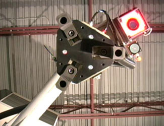
In the bin picking operation, thread protectors are packed in bins in layers divided by cardboard sheets. The machine vision system rides on the robot arm. The vision system consists of a Basler Ace camera that interfaces over the GigE Vision® interface standard for high-performance industrial cameras with a frame grabber card on a Beckhoff industrial personal computer. A Tectivity light emitting diode (LED) inside the camera enclosure generates red light that helps overcome ambient lighting to capture the image.
JMP programmers wrote a graphical user interface for the workcell in Visual Basic that performs vision operations by calling vision tools from the Cognex VisionPro® library. VisionPro provides pre-configured, tightly integrated acquisition support for the complete range of industrial cameras and video formats. Its QuickBuild™ application development environment makes it possible to configure acquisition tools, define vision tasks and make pass/fail decisions without any programming. The VisionPro library includes tools such as PatMax®, PatInspect®, PatFlex®, IDMax®, and OCVMax™, that gauge, guide, identify and inspect parts despite variations in part appearance due to the manufacturing process.
Traditional pattern matching technology relies upon a pixel-grid analysis process commonly known as normalized correlation. This method looks for statistical similarity between a gray-level model — or reference image — of an object and portions of the image to determine the object’s X/Y position. Though effective in certain situations, this approach limits both the ability to find objects and the accuracy with which they can be found under conditions of varying appearance common to production lines, such as changes in object angle, size, and shading.
Cognex's PatMax geometric pattern matching technology learns an object’s geometry using a set of boundary curves that are not tied to a pixel grid and then looks for similar shapes in the image without relying on specific gray levels. The result is a significant improvement in the ability to accurately find objects despite changes in angle, size, and shading.
The Motoman HP50 robot moves the camera above the bin and signals that it is in position to take a picture of the bin. The PLC passes a request to the vision system to take a picture. The camera takes the picture and the PatMax vision tool identifies the location of each thread protector in the bin. The vision system then identifies the thread protectors in the image and calculates the location of each one. The Visual Basic interface makes the conversion from pixels in the camera image to millimeters required by the robot control system.
The PLC then directs the robot to pick one of the thread protectors from the bin. The thread protectors come in 11 different sizes ranging from 4 inches (10.16 cm) to 8 inches (20.32 cm) in diameter. The vision system is trained on each different part number. It not only identifies the location of good parts but also detects the presence of parts of the wrong size that are intermingled with good parts.
Assembling thread protectors to pipe
The robot hands off the part to a second Motoman HP50 robot that performs the task of assembling the thread protector to the pipe. The PLC stores the position of all of the parts in one layer of the bin and commands the robot to pick them up one by one. When the bin is empty the robot removes the cardboard divider and the camera takes an image to determine the location of the parts in the next layer.
The second robot carries the thread protector over to a fixture where the oil tool assembly is located, exposing the sections of pipe where a thread protector is to be installed. “Assembling two threaded fasteners is a challenging operation for a robot because the robot does not have the human operator’s ability to feel the connection between the threads”, said Kevin Ackerman, Machine Vision Specialist at JMP Engineering. “The vision system helps overcome these challenges.”
A Basler Ace camera attached to the second robot locates the pipe for thread protector installation. A Smart Vision Brick red light shines on the pipe at an oblique angle to create a shadow that enables accurate measurement of the pipe diameter. The VisionPro circle tool is then used to check the diameter of the pipe to makes sure it matches the thread protector and also more accurately determine the location of the pipe. The robot arm is equipped with a compliance device that allows the pipe thread to pull the arm and the thread protector as it screws onto the pipe.
The most recent camera image is displayed on the screen along with results such as the size of the thread protector and size of the pipe. The part picking robot image and results appear on the left side of the screen and the thread assembly robot image and results appear on the right. A configuration menu enables the operator to configure the camera.
The automated calibration procedure takes advantage of a fixed, permanent target located near each robot. The camera mounted on each robot acquires four images of the target and between taking each picture moves a known distance. Based on these four images, the calibration routine determines the position of the robot in relation to the target. “Calibration is a manual process that is executed on demand whenever someone believes that one of the robots has become inaccurate, perhaps because of a bent gripper or the camera was bumped out of position,” Ackerman said. There’s a good chance this application will lead to a new generation of vision enabled robots that will help improve productivity and quality in the oil tool industry.”